
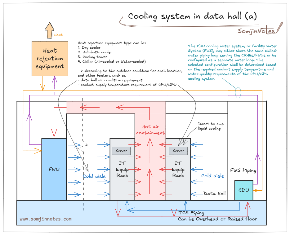
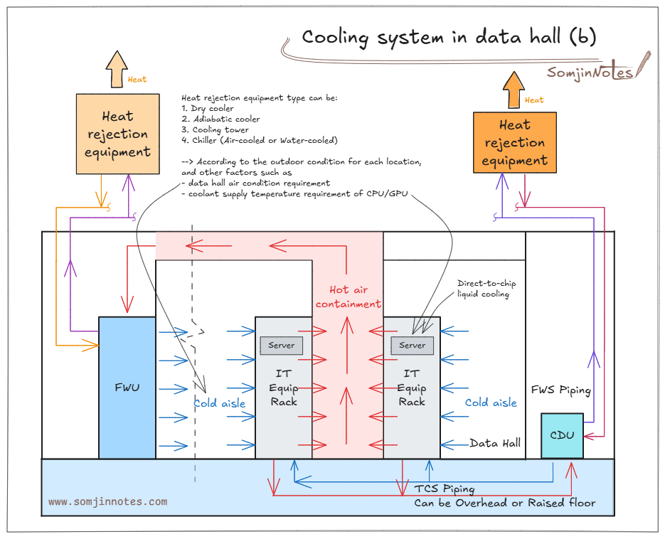
This visual note shows a hybrid data center cooling topology for data hall having direct-to-chip liquid cooling.
Key Components & Heat Paths
Air Cooling Loop (Data Hall): Cold air flows through the cold aisles into the IT equipment racks. Hot exhaust air is trapped via hot air containment and routed back to the Fan Wall Unit (FWU) for re-cooling.
Liquid Cooling Loop (Direct-to-Chip): High-density CPU/GPU chips are cooled directly using fluid served by a Coolant Distribution Unit (CDU) via Technology Cooling System (TCS) piping (installed either overhead or under a raised floor).
Facility Water System (FWS): Transfers heat from both the FWU and CDU to the central heat rejection loop (a) or using a dedicated cooling loop (b).
Heat Rejection Equipment: Heat is rejected to ambient air using dry coolers, adiabatic coolers, cooling towers, or chillers (air-cooled or water-cooled).
Notes:
- Integrated vs. Dedicated FWS Loop: The CDU cooling water circuit can either share the main chilled-water plant with air-handling units (CRAHs/FWUs) or operate as a dedicated loop. The choice depends on required coolant supply temperatures (warm water cooling vs. chilled water) and strict water quality specifications needed for liquid-cooled cold plates.
- Heat Rejection Selection: Selection of the outdoor heat rejection technology depends heavily on local wet-bulb/dry-bulb ambient conditions, server supply temperature limits, and target PUE.
Related notes:
Cooling system in data hall for liquid-cooled rack (Direct-to-chip liquid cold plate)
Air distribution in data hall for air-cooled IT racks
Data center Rated or Tier classification – Mechanical System
Leave a Reply